


Create an AutoCAD plugin using cSharp to compute the Shortest Path Matrix in a graph


Article's Purpose
Autodesk AutoCAD is a widely known program by engineers and designers used to create 2D and 3D models, it has a great interface with lots of options. It's an intuitive easy-to-learn software which allows the user to achive great results fastly. CAD stands for Computed-Aided-Design, and Auto for Autodesk. Last stable version has been launched on 2022.
At the same time, being able to use AutoCAD through programming can give us a powerful tool to solve many problems. This article explains how to do this. We'll use .NET AutoCAD API to create a plugin that will compute the Shortest Path for a given graph, from each node to every other node (using Dijskstra Algorithm).
Input and output of our plugin
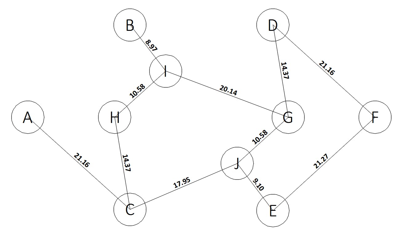
Our input is an undirected graph where the edge weights correspond to their length.
The output we want to get are 2 tables:
- Shortest path
distancefrom each node to every other node. - Shortest path
routefrom each node to every other node.
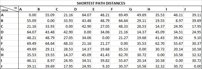
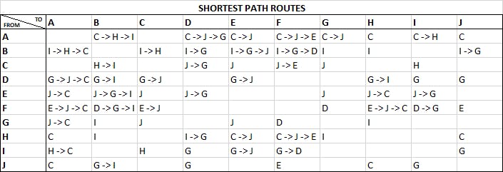
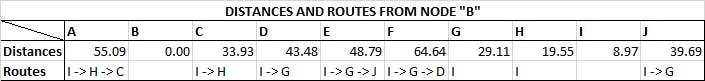
Now, for example, if we want to know the shortest path between B and E, we know the shortest route is B → I → G → J → E and the length of that path is 48,79.

Our very first plugin with cSharp
Here we'll make a very simple plugin where, once loaded in AutoCAD, will respond to the command hello and draw the following circle in the model. This will be useful to learn the first steps to create any .NET plugin for AutoCAD.

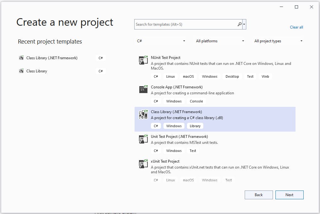
First step is download and install Visual Studio Community, then create a fresh new project selecting c# Class Library for .NET Framework, we can name it MyFirstCadPlugin.
Once new project is created, then we need to add AutoCAD dll references to access the .NET AutoCAD API. These references are listed below, and located in the Program Files folder, where AutoCAD is installed.
- acmgd.dll
- acdbmgd.dll
- accoremgd.dll
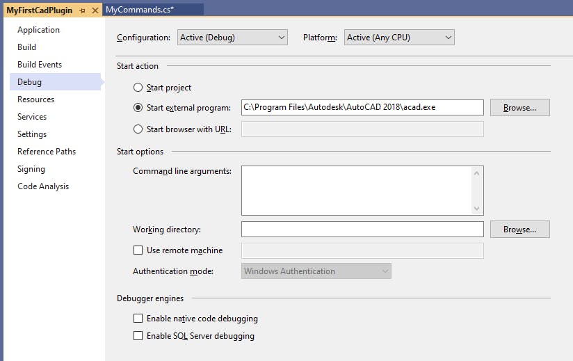
Now we have to configure the debug project properties, setting the option start external program to start AutoCAD (acad.exe) while debugging.
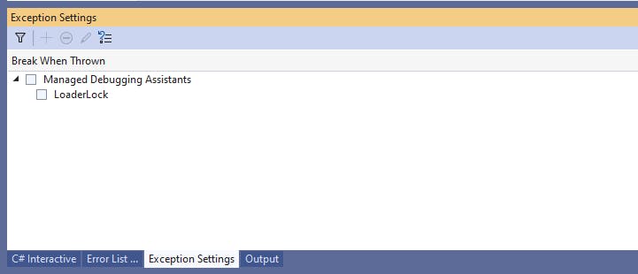
Next we should uncheck loader lock in the Exception Settings in order to allow Visual Studio to execute AutoCAD while debugging.
We can use the following code in Class1.cs to create the plugin. This code, as its explained in the comments, first connects to the active AutoCAD document and database, then creates a transaction where a Circle and Text entities are defined.
Finally, if we press Start in Visual Studio, new AutoCAD instance will appear, then we can load our plugin typing the "netload" command and searching for the MyFirstCadPlugin.dll, stored in /bin/Debug, in our cSharp project files. Once loaded, by pressing hello in the command bar, the circle with "hello!" inside will appear in the model!
Shortest Path Matrix plugin interface
We already know how to create a basic .NET plugin for AutoCAD, so we can go deeper and focus in our real goal, which is to create a program that will compute the Shortest Path Matrices for a given graph. The following windows form summarizes the functionality of the program.
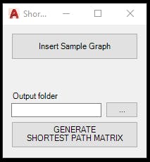
Here is explained how it works:
Insert Sample Graphbutton will draw into the model a sample graph. This is useful to show the user an example to try the program. In order to use a custom graph, block nodes should same type as in the sample graph (block's name: "node", and with a text label).Generate Shortest Path Matrixbutton will prompt the user to select a graph, and then will generate the output matrices and save them as CSV files in the selected folder by the user.
Drawing a Sample Graph into the model
Using AutoCAD elements to describe a graph
We know a graph is composed by a set of edges and nodes, but we have to use AutoCAD elements to represent them. The edges can be easily treated as Lines or Polylines, but for the nodes there is not such a direct AutoCAD object. Every node has 2 properties: position (x and y), and label, for example, the following picture shows a node where label = "B", and position (x = 138,89, y = 169,11).

There is an element in AutoCAD that can be used to represent nodes in a very simple and natural way, and it's called Block. We will create a custom block with the desired shape to use it to represent the nodes.
The following code (commented below) is used to create custom blocks in cSharp.
These are the main functions:
CircleBlockNodeEntities
This method returns a list of entities to create a block node shaped by a circle and a letter inside. There are 2 entities in this block: circle and text.LeaderBlockNodeEntities
Returns a list of entities to create a block node shaped by a leader line with its label above, like the following picture. There are 3 entities in this block: polyline, circle, and text.

InsertBlockNodeToDb
This method creates a block into the current model database, uses as argument the list of entities returned by one of the methods explained before, and the name we want to give to that block. For example, the following code will create a block named "node", with theCircleBlockentities.
List<Entity> blockNodeEntities = BlockNodeCreator.CircleBlockNodeEntities(acCurDb, new Point3d(0, 0, 0));
BlockNodeCreator.InsertBlockNodeToDb(bt, acDoc, acCurDb, "node", blockNodeEntities);
DrawBlockNodeToModel
This function draws into the model a block node, receives as arguments the block's name, label, and its position. For example, the following code will draw a block named "node", with the label "B" in the (20, 100, 0) position.
DrawBlockNodeToModel(bt, acBlkTblRec, "node", "B", new Point3d(20, 100, 0));
Inserting a sample graph into the model
We have solved the way we are going to represent a graph through AutoCAD elements, now we have to add some functionality to draw an entire sample graph. But… from where are we going to read the info to draw that sample graph? Or… How are we going to tell the program the set of edges (polylines or lines), and nodes (blocks) to be drawn?
Here is where CSV files (tables), can help us to do the job. The sample graph will be described with 2 separate csv files, one for the nodes, and another one for the edges, they will be structured as follows.
nodes.csv
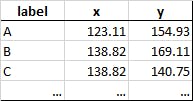
edges.csv
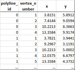
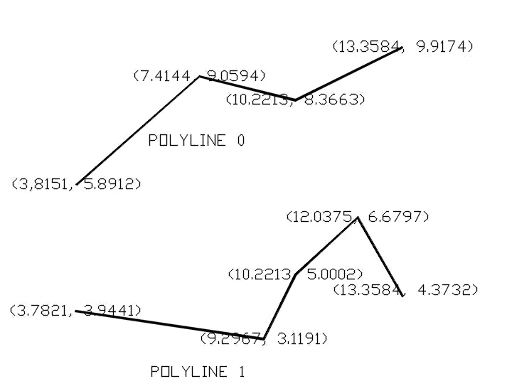
Where each row of nodes.csv defines a node, with its label and position, and edges.csv has the information of a polyline vertex. These CSV files are embedded files in the Resource Folder. Next image corresponds to the 2 polylines defined in the above table:
With these 2 CSV files and the appropiate code to read them we can draw any sample graph into the current AutoCAD model. Next is presented the code to do this.
This code can be summarized as follows:
- Function
GetNodesreads the corresponding csv file and return a list of nodes. - Function
GetEdgesreads the CSV file and return a dictionary where keys are thepolyline_idand values arePolyline AutoCAD objects. Function InsertSampleGraph draws into the model the sample graph defined by the CSV files, through the 2 functions defined above. - Function
InsertSampleGraphdraws into the model the sample graph defined by the CSV files, through the 2 functions defined above.
Performing Dijkstra to compute the Shortest Path Matrices
So far we know how to represent a graph with AutoCAD, and how to plot a sample one. It's time to attack our main goal, which is, for a given graph, get the Shortest Path Matrices (one for the shortest distance, and the other with the path to achive that distance.
First we need to prompt the user to select a graph in the model, we do this through the following piece of code.
This code prompts the user to select the graph, then returns an array of ObjectId with all the selected elements. This function is pretty reusable for other AutoCAD plugins we want to build, because often we'll need the user to select something in the model.
Next is presented the code to perform Dijkstra and save the Shortest Path Matrices as CSV files.
The logic this code follows is:
Filter the
ObjectIdarray that comes from theGraphModelSelectorfunction presented above. Every polyline and line will be converted to anEdge, and every block node to aNode.Generate
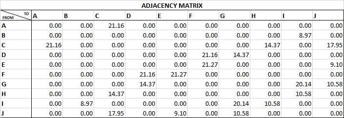
Adjacency Matrixfrom the list of edges and nodes. We create a dictionary from the nodes list, where the key is a Tuple with the coordinates point, and the value is a Tuple with node's label and index. Then, if we iterate for every edge, and check if both itsstart_pointandend_pointare a key in the dictionary, we can update the adjacency matrix because that points are connected at a distance as the edge length. Next piece of code explains this (see lines 117 to 140 from the previous gist). Below is presented the adjacency matrix for our sample graph.Build a function to perform Dijkstra algorithm having as an argument the adjacency matrix, the starting point, and the node list. This function is called
PerformDijkstraas you can see in the above gist, and will return an array of the structDistanceAndRoute. For example, if we invoke the function for the second node (labeled B), will return an array with the shortest distances from node B to every other node, and another array with the routes associated to that paths. See picture below.Finally we
PerformDijkstrafrom every node in order to obtain the output we want.GenerateShortestPathMatrixdoes this job and returns as an output the Shortest Path Matrices into 2 CSV (one for the distances, and the other for the routes).
And that's it! We've built the plugin and it does exactly what we wanted!
Building a solution and loading it into AutoCAD
Once we are sure we have tested our program it's time to move from the debug mode into release mode, we can change this in the menu Build → "Configuration manager".
In order to load the plugin, we open AutoCAD and type "netload" in the commands bar. Then a menu will show up, we must search into our project files, in the Release folder we select the dll with the projects name, for exampleShortestPathMatrix.dll`.
Now we can type shortestpath in the command bar, and our form will appear! Our plugin is ready to be used!
I hope you liked reading this article, as I said in the beginning, being able to use AutoCAD by coding is a powerful tool we can use to solve many problems. In this Github repository you can find all the project files.
If you enjoyed this story, please click the 👏 button and share to help others find it! Feel free to leave a comment below. You can connect with me on Medium, LinkedIn, Twitter, Facebook.